Heating Up: Modeling Hotspots on Aerospace Structures
By Charles Cervi
Achieving flight is one of the greatest technological advancements of our time. At high speeds, aerodynamic forces such as drag can cause parts of the plane, such as regions on the panels of a wing, to heat up. But why does this matter?
These regions, called “hotspots,” can pose serious problems for flight. Heat causes structures to expand proportionally to the increase in temperature. In the case of a constrained structure, such as a panel on a plane wing that is secured with rivets around the perimeter, the expansion must go somewhere. This causes the panel to buckle, noted by a large lateral deflection. If the temperature distribution of the panel is not uniform and contains regions that are hotter than others, the deformation can focus around those hotter regions. This alone is not necessarily considered a failure – many structures can operate in the postbuckled regime with one example of an aircraft exhibiting this is the B-52.

However, the buckled panels can lead to operating conditions that a structure might not be designed to experience. The result of this could be relatively harmless such as inefficiencies due to increased drag or other more serious problems that result in failure. The slight differences in the thermal field can cause the panel to deform in vastly different shapes. For this reason, it is important to be able to accurately model the potential thermal fields seen during flight.
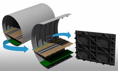
Why Stiffened Panels?
Spaceflight has a massive weight penalty associated with it. That is, increasing the weight of the aircraft results in a dramatic increase in flying expense. The increase in weight means more fuel and power are required to fly. For this reason, aerospace engineers seek to minimize weight by using slender structures while at the same time ensuring the safety of the plane. A common structure is a stiffened panel as it provides a dramatic increase in strength from a flat panel with a minimal increase in weight. In the case of panels, they can operate in the postbuckled regime and depending on the loading they may have multiple equilibria. Many different types of stiffeners are possible and can be chosen based on the expected loading they need to withstand. Grids of stiffeners are often used as well for increased rigidity.
The Setup
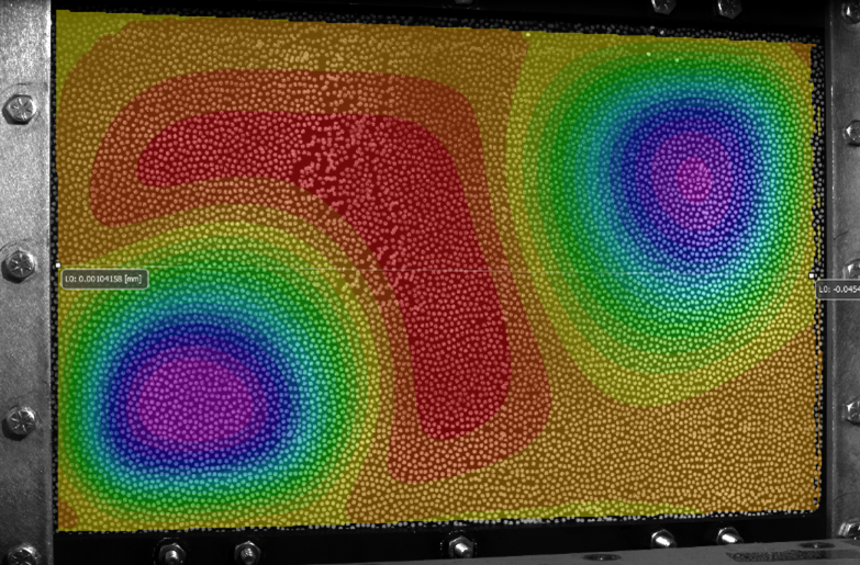
To capture high-quality data of the temperature profile of our stiffened panels and associated deformation during our experiments, it is important to use advanced test equipment. During experimentation, I captured both the thermal field of the panels, using a Forward-Looking Infrared (FLIR), camera as well as deformation, using digital image correlation cameras (DIC). These tools are incredibly powerful – they can record minute differences in temperature or deformation that we can’t perceive with our eyes. In this work, I applied a localized thermal load, using a small but powerful heat lamp, approximately in the center of the stiffener until the maximum temperature was around 200°C. I then removed the thermal load (heat lamp), recording data as the panel cools. Using the temperature data acquired from FLIR, I then used that data in a simulation to model the effect of the thermal load on the panel to compare with experimental results.

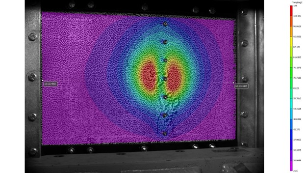
While experimental data is incredibly useful for designing structures, it can require extensive data acquisition and numerous experiments to gather ‘good enough’ data to make decision decisions. However, by running a few experimental cases, researchers can acquire the important data, such as the thermal distribution, and apply that to models to simulate the effects of the loading. This project used Ansys, a finite element solver, to simulate our results. For each simulation, the temperature profile of each panel (which was captured experimentally using FLIR cameras) was enforced on our panels. I then simulated how the panel deforms as a result of each temperature profile. This process is repeated as the panel cools down to ambient temperatures.
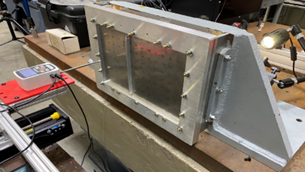
For the experiment, I took four stainless steel panels and placed aluminum stiffeners in three of them. I used two types of stiffeners and placed them in different locations in order to analyze how these conditions changed the response of the panel. I then placed each one into a test frame and secured the perimeter using a series of bolts. A small, heat lamp was then placed in front of the plate, centered around the stiffener of the panels (or the center of the unstiffened panel). I then turned on the heat lamp for a period of time until the temperature of the panel had increased significantly. After some time, the heat lamp was turned off and removed, and the data acquisition system recorded the deformation of the panel as well as the temperature as the panel cooled. I repeated this process, forcing the panel into another equilibrium that is not normally observable. This data was then used to create simulations to try and model the same process.
For the multiple panels tested, simulations were performed and showed strong agreement with the experimental results. A sample case using a light stiffener is shown below where I plotted the increase in temperature against deformation term β. The β term is a measure of the panel’s symmetry (or lack thereof) in the deformation and can provide qualitative information on the global shape of the structure.
In this figure, there are two distinct ‘paths’ that the behavior falls in: the red/black and the green/purple. These paths correspond to different equilibria and have different deformed shapes due to the loading. The structure naturally deforms in the red/black path (called ‘primary’), but perturbations can cause it to jump into another ‘remote’ configuration such as green/purple. The red and green correspond to experimental results while the black and purple are from simulations.
As we can see, there is overall very strong agreement between the experimental and simulation results for each path. Some slight discrepancies exist between the exact deflection associated at each temperature, but qualitatively the shapes and behavior match quite well.
Localized thermal loading is a difficult problem to model and to accurately describe. Slightly different load cases can lead to dramatically different results. For instance, if a heat lamp was placed in a different position, we would expect a very different deformation profile as a result. Furthermore, assigning a relevant thermal parameter can be difficult. For instance, the average temperature, while a useful property of a structure, doesn’t really give much information about the local effects from focused thermal loading. However, we have shown that if experimental thermal data is carefully acquired, it can be used to accurately the model the behavior of real-world structures – paving the way for more complex analysis in the future.

Future Work
In this project, I primarily focused on using a single heat source, centered on the stiffener. In the real world however, the temperature profiles are not necessarily this simple and can be much more complex. There are several avenues that could be taken after this project. Different thermal distributions would be an interesting problem to explore as it is evident that the thermal load has a significant effect on the deformed shape. Similarly, the focus of this work was on one type of stiffener arrangement. Exploring more complex stiffener arrangements that are seen in aerospace would give greater insight into the structural response of aircraft. That is, if the expected thermal loading is known and can be modeled, different stiffener arrangements can be created and tested earlier in the design process.
Charles Cervi is a Ph.D. Candidate in Mechanical Engineering at Duke University. He is a North Carolina Space Grant Graduate Research Fellow.